Demystifying ST Maps
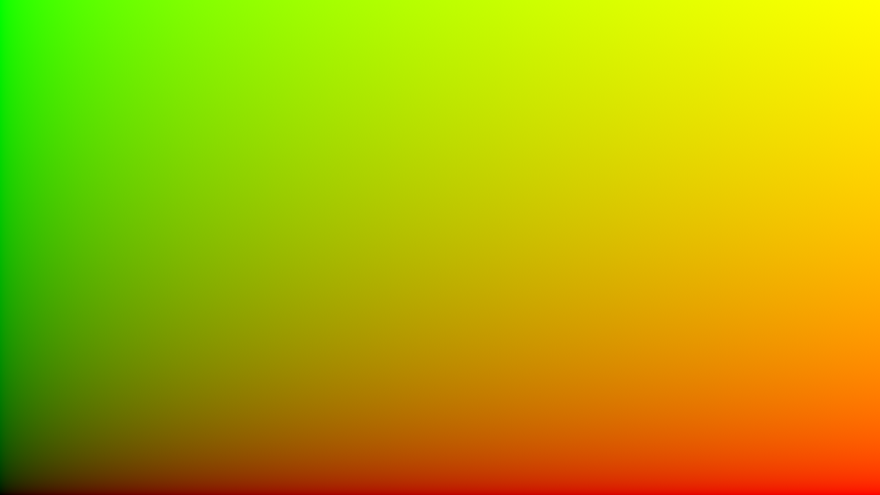
Knowing what an ST map is, and how you can use it to your advantage, quickly pays dividends when working in Nuke.
An ST map is an image where every pixel has a unique Red and Green colour value that corresponds to an X and Y coordinate in screen-space (pictured above). You can use one to efficiently warp an image in Nuke.
You will sometimes see ST Maps looking like this:

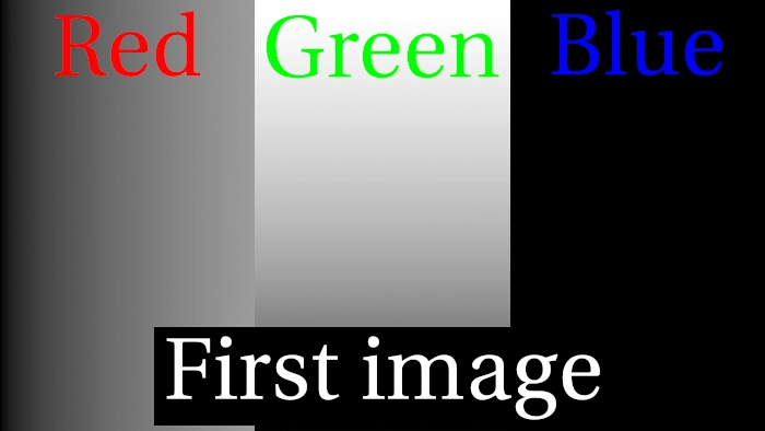
Visually, there is a huge difference, but when you compare the RGB channels, you’ll notice that Red and Green, the channels defining the X and Y coordinates, are identical. The only difference is we have a Blue value of 1, which has no effect on what ST / UV images do.
What’s the difference between ST Maps and UV Maps, anyway?
ST maps and UV maps look and function exactly the same way in Nuke, so it’s pretty difficult to discern the difference. Out of curiosity, I did a bit of Googling and asked a bunch of smart colleagues what they knew, although the answers I got were pretty vague. While there doesn’t seem to be a clear answer about the "why", I did uncover some interesting knowledge about the "what"!
UV Maps refer to X and Y coordinates, so it would make sense to call them XY Maps. Although in CG terminology, usage of XYZ is reserved to denote an object’s position in 3D space. U & V were the next-closest letters that made sense, and hence were used…
ST Maps (the next, next closest letters) are parametric coordinates that originated in earlier versions of Renderman. Technically, UVs are used for texture coordinates (object space), and STs are used for surface coordinates (texture space).
So what this means for Compositors using Nuke is, we use "ST maps" as we’re using them in relation to textures/images, not 3D geometry.
How to create ST Maps in Nuke.
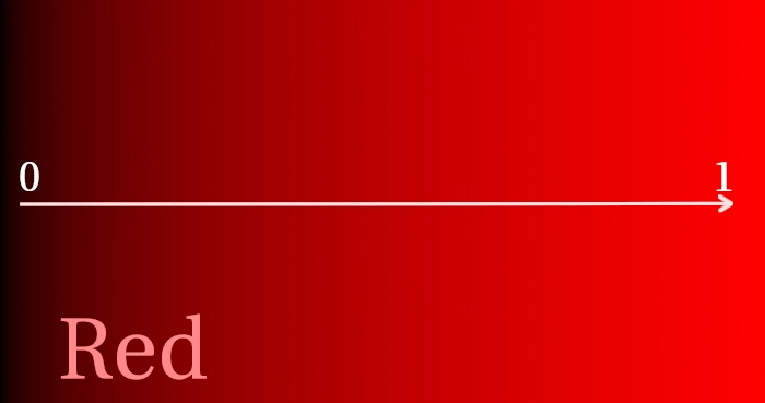
ST Maps are bi-directional. On the X-axis, the left-most pixel has a red value of 0 and the right-most pixel has a value of 1. on the Y-axis, the bottom-most pixel has a green value of 0 and the top-most pixel has a value of 1.
You can achieve this by plussing two ramp nodes together, using the following settings:
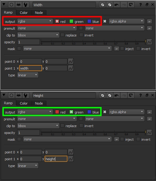
- Typing
widthandheightinto the appropriate knobs will return the format coming from the nodes' input. - Typing
root.widthandroot.heightwill always return the Project Settings' format.
The second way is far easier, but a little more technical. You can create an ST Map from scratch with an Expression node, like so:
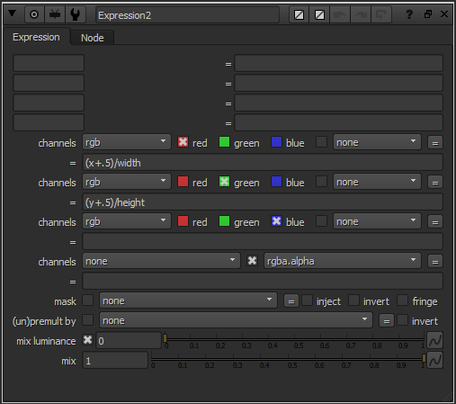
When we create an ST Map with the expression node, the X and Y coordinates are referring to the bottom-left corner of each pixel. We add 0.5 (half a pixel) to offset the coordinates, so they’re correctly located at the centre of each pixel. You can see the difference in the gif below.
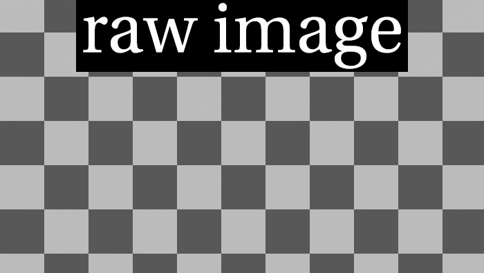
Warping images with an ST Map.
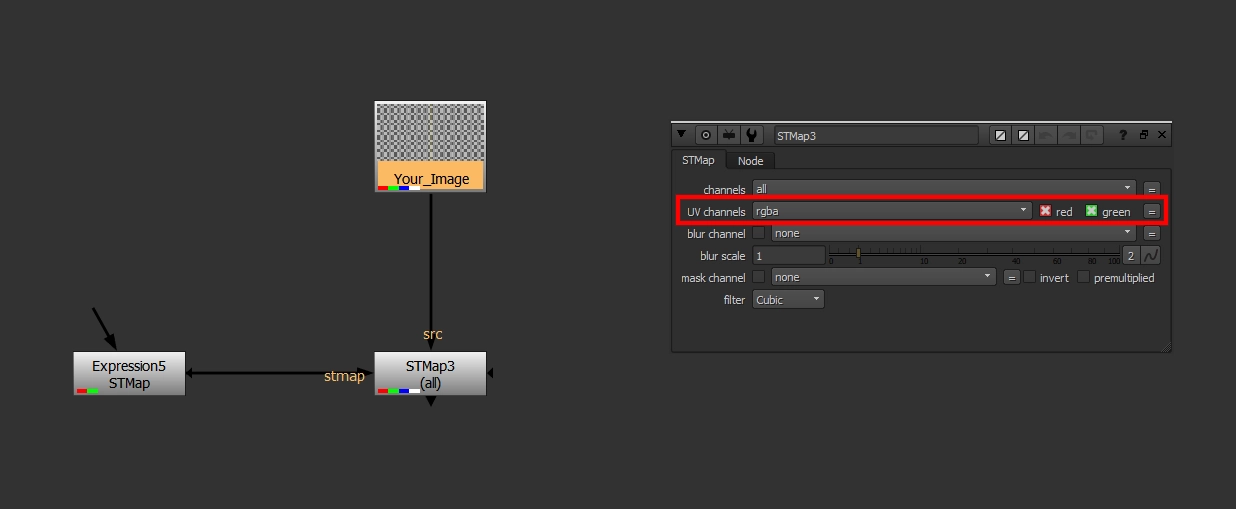
You can warp an image efficiently in Nuke by using the appropriately-titled STMap node! Note that you must set the UV Channels knob in the STMap node to rgb or rgba before it will pick up the Red and Green channels from the ST Map plugged into the node’s stmap input. It’s kind of silly that this isn’t the default knob value, but you can easily change this in your menu.py.
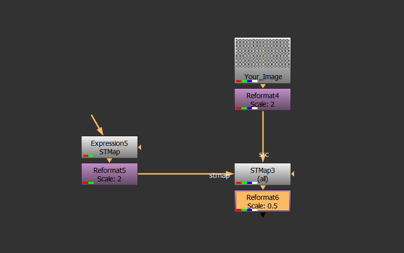
Since ST Maps are based on whole-pixels, they can sometimes filter images in unwanted ways. Thankfully, there is an easy fix to retain image fidelity! Simply reformat your input image & ST map to a higher resolution before the warp, and reformat back to regular resolution afterwards, like so:
Lastly, whenever you pre-render an STMap, be sure to render 32-bit EXRs to retain the full & correct information in your ST Map.
Now that we have the theory & basic setup out of the way, what practical applications does ST Mapping have in Nuke?
Lens Distortion.
Seemingly every camera tracking software on the market today has its own way of getting lens distortion data into Nuke. Some programs export ST/UV Maps, whereas other more-popular options such as 3DEqualizer have their own nodes to use in Nuke.
This can be a problem when packaging a Nuke script to send to a stereo-conversion vendor, as proprietary node sharing is frowned upon. To get around this, you can create a new ST Map, apply 3DEqualizer’s Lens Distortion node to it, then pre-render the distorted ST Map as a 32-bit EXR. The node setup pictured above will then apply your lens distortion the same way as the proprietary node!
Note: I recommend doing this conversion at the tech check stage, so the finalled version of your comp includes the STMap-based Lens Distortion. Visually, the results will be near-identical, although when doing a difference between the STMap node & any Lens Distortion node, there will be very minor differences due to filtering.
Blending two different warps.
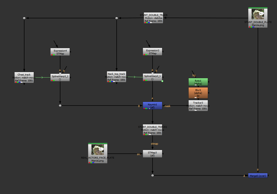
SplineWarping, GridWarping, or any other type of warping in Nuke can be pretty tedious, especially when trying to do it all in one node. As a real-world example, warping an actor’s head to stick to a stunt-double’s body requires a few different tracks & splinewarps.
Using the setup pictured below, we’re able to:
- Track the general motion of the stunt double, and apply the data to an ST Map (STUNT_DOUBLE_TRACK1).
- Track specific features of the stunt double from a stabilized plate (using an inverse of the aforementioned Tracker), and plug that data into SplineWarps.
- Now you can draw a shape in the SplineWarp that should pretty-closely track with the plate, meaning you will only need minimal keyframes to warp things to where they need to be.
- Lastly, we’re keymixing between two warps. Any "blurry" pixels will effectively dissolve from one warp to the other, without ghosting — this is where the real power of this technique is!
Fixing SmartVectors with warps.
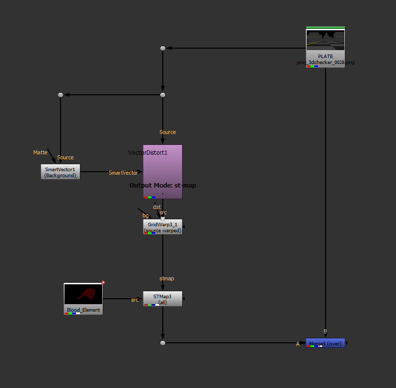
I’ve utilized SmartVectors & VectorDistort quite often in the past year to track textures and elements onto organically-moving objects. A lot of the time, SmartVectors do a pretty good job, but the node doesn’t offer much in the way of flexibility when needing to tweak the results & push a shot across the finish line.
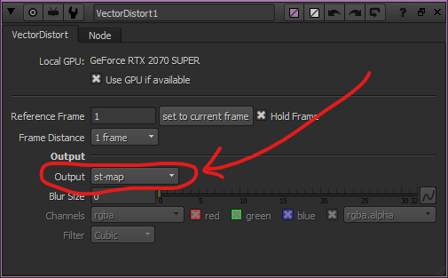
Utilizing ST Maps in conjunction with SmartVectors has saved me many times in the past! For example, the setup below is using a GridWarp to tweak my almost-working VectorDistort:
Speeding up projection-mapping.
We’re all familiar with how to use Project3D to project an image onto geometry. Although when working with dense geometry, it can take an age for the ScanlineRender node to crunch the data.
To speed up this process, we can feed an STMap into said projection, and precomp the result!
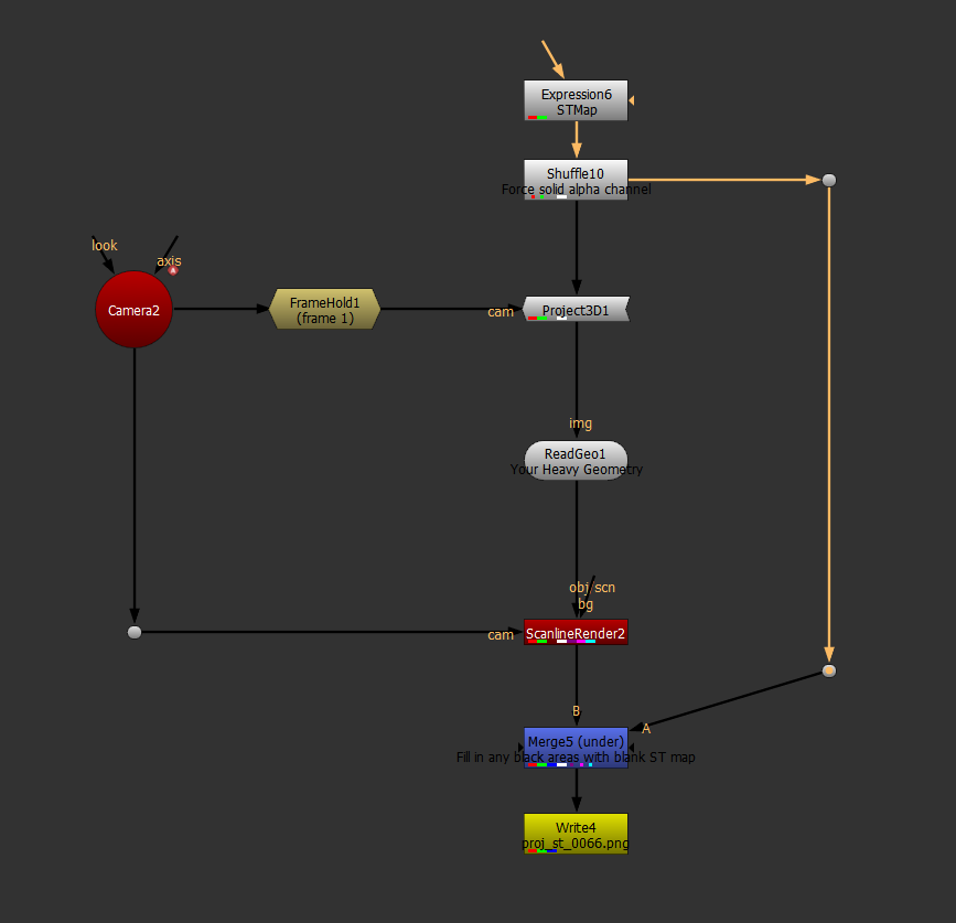
Once you have a pre-rendered ST Map, it’s possible to invert it to get rudimentary image stabilization, or change the "Reference Frame" like you would in a Tracker node…
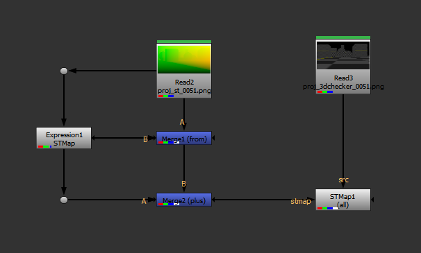
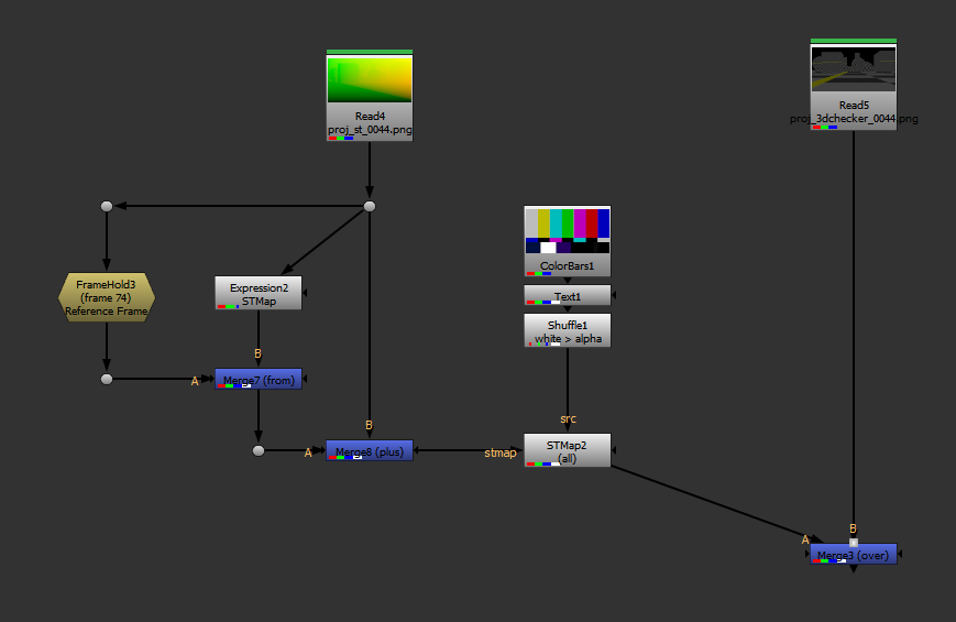
… but as you can see, the results aren’t particularly viable. This is because we’re dealing with overlapping geometry in our projection, and when that data is re-mapped, there is no extra data to fill in the gaps.
If you absolutely have to invert or remap an ST Map to a different reference frame, there are some clever gizmos on Nukepedia (which I’ve linked to in the useful resources section at the end) which utilize PositionToPoints in an attempt to remap / invert ST Maps in a more-predictable way. While the results aren’t perfect, they’ll do a better job than my setups above!
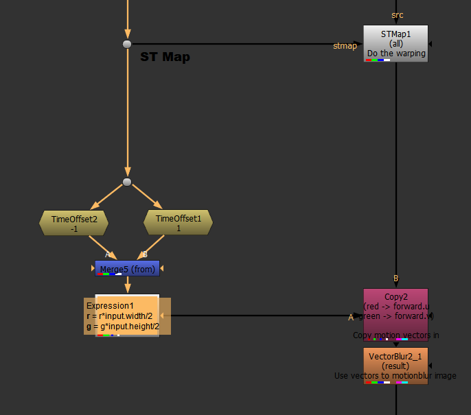
Generate motion vectors from your ST Map.
SmartVectors & VectorDistort are great for tracking images to an organically-moving plate, although it comes without motion blur. We have a couple options:
- Run the MotionBlur node on the result to calculate an approximation of the moblur.
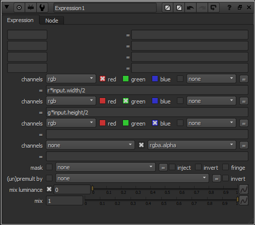
- Create our own motion vector pass from the existing ST Map. You can do so with the setup pictured below.
Wobble 2D fire elements based on a Transform.
Saving the best for last — I recently discovered this awesome tutorial from Han Cao, where he uses a stack of incrementally-time-offset ST Maps to re-animate a fire element’s wobble based off a user-animated direction of travel. This is probably the most inventive use of ST Maps I’ve seen! Check out the tutorial here:
That's it for this blog post! See below for further reading on this topic!
Useful resources & further reading.
- This paper from Duke University.
- Discussion on StackOverflow.
- Understanding UVMaps - Warping with STMap (Part 1).
- Understanding UVMaps - Warping with STMap (Part 2).
- Projecting STMaps by Marcel Pichert.
- Foundry forum post discussing ST Map Inversion.
- Smarter SmartVector tutorial from Han Cao (his custom gizmos for blending ST Maps are on Nukepedia, although they don't work in Nuke 11 and above. Using the knowledge above, I'm sure you'll be able to figure out how to blend between more than one ST Map!)
Useful gizmos.
- in_InverseSTMap from Luca Mignardi.
- STMap Reference Frame from Marcel Pichert (a little more complex than my quick solution above).
- STMap_Extend from Han Cao, which gives you overscan for your ST Map.