Understanding the ColorMatrix node

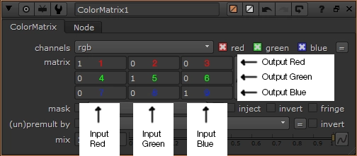
Each row of knobs represents a colour channel. For example, the output of the red channel is the result of knobs:
1 (input red), 2 (input green) and 3 (input blue), being added together.
In English, the above image reads:
For the red channel, output the result of ((R * 1) + (G * 0) + (B * 0))
For the green channel, output the result of ((R * 0) + (G * 1) + (B * 0))
For the blue channel, output the result of ((R * 0) + (G * 0) + (B * 1))
Because we're using 100% of the red channel for output red, 100% of green for output green and 100% of blue for output blue, the output image will look identical to the input image.
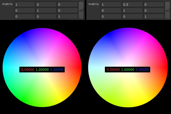
If we were to change knob 2 from the image above to a value of 0.5, a pixel in our image with a sampled value of 0.00000, 1.00000, 0.00000, would turn into 0.50000, 1.00000, 0.00000. We're essentially taking 50% of the green channel, converting it to the red channel, then adding it back to itself, which causes the greens to be more-yellow. The image below is a more-visual representation of what's going on.

So, when should you use a ColorMatrix node? It's most useful for transforming colourspaces, although in certain cases, I've found it incredibly useful when grading fire elements & FX renders into a more natural range of colours.